

Case History
Excavator Mounted Pile Driving System for Roadway Shoring and Bridge Pile Installation

Excavator Mounted Pile Driving System for Roadway Shoring and Bridge Pile Installation
Project Snapshot
- Development of Excavator Mounted Lead System - EML30
- ORBA Transportation Infrastructure Innovation Award 2018
Genesis of the EML30
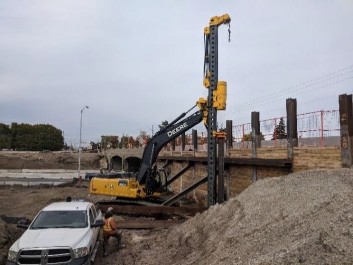
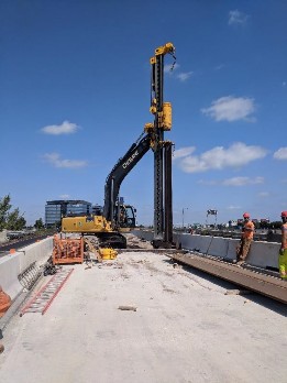
The Genesis of the EML30 Excavator Mounted Lead for 30 ton Excavators originated in two places – Bermingham Construction and Berminghammer Equipment divisions separately. Bermingham (Contractor) had been approached by several general contractors requiring shoring and bridge foundation work in Northern Ontario (1,000+ km away from Bermingham’s Hamilton office). They would ask if there was anything Bermingham could do to lower their price on foundation elements. Bermingham explained that the cost of the work was relatively minor to the cost of mobilizing/demobilizing the equipment to the remote site 1,000+ km away. The costs associated with transporting a crane to the remote locations were significant. Some cranes that would complete similar work require as many as 3-4 truckloads to transport them to a construction site. This meant transportation and setup costs could total over a $100,000 for a single project in cases when there were many remobilizations or many structures. Knowing that the crane mobilization was highly cost prohibitive; Bermingham conceptualized a piling lead that could attach to an excavator, even an excavator that would likely already be on site working with the General Contractor. This meant that the entire piling system could be transported on either a truckload by itself or in combination with the excavator on a float in its entirety. Concurrently Berminghammer had been approached by several contractors in the United States and Canada to design and manufacture several custom excavator mounted lead systems for similar applications.
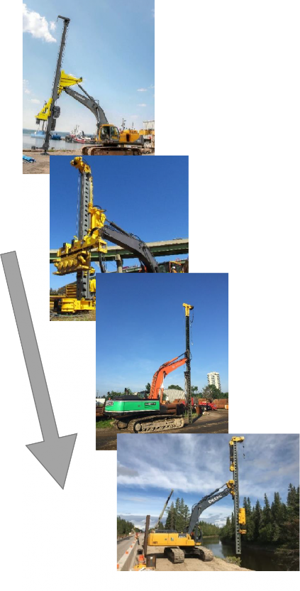
With the momentum from both sides of the company as well as a local piling project ready for a trial, Berminghammer began work on a prototype. In 2008 Berminghammer developed a small, crane-mounted semi-fixed pile driving unit for the U.S. Army and manufactured 130+ units. The first EML prototype utilized the lead components of the army system and attached them to an excavator. This concept allowed Berminghammer to identify areas for improvement. An example was the ability to level the lead for uneven ground conditions as it was determined to be very labour intensive to block up the excavator on uneven ground.
Implementation
Initial Release for Production
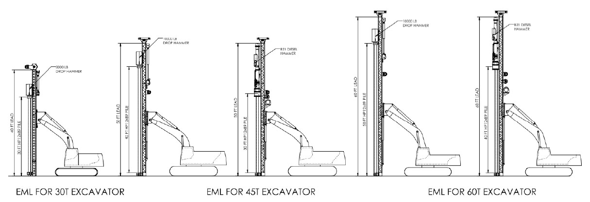
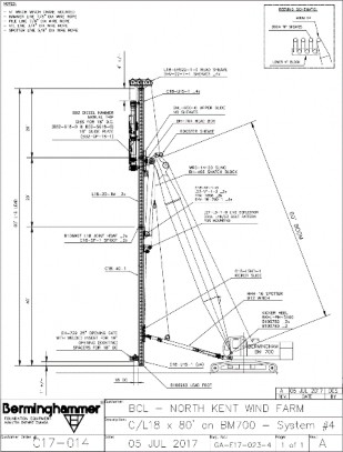
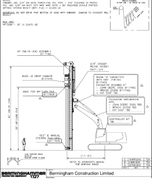
The EML30 was actioned for full engineering design in January of 2018 under the principal Engineer Tyler Hilsden P.Eng. It was the first of a product line of EML’s conceptualized by Berminghammer engineers. The entire product line can be observed conceptually in Figure 1. There were to be three different piling models for 30, 45, and 60 ton excavators. The larger the excavator, the larger the single length of pile that could be driven.
By February, BOT Construction had made a commitment to order the first unit for a project that they had recently won; MTO 2017-5128 located about an hour west of Hearst in Northern Ontario. The project involved the replacement of three culverts to be done in stages. A shoring system was required to support the highway above while removing and reinstalling a new culvert. Berminghammer engaged a geo-structural firm to design a shoring system to pair with the features of the EML30. The design resulted in a combi wall system involving H-Piles to be driven first followed by sheet piles in between them. This design would divert water around the excavation allowing the culvert replacement to take place in a drier environment. The outer sides of the shoring system were done by traditional H-pile and timber lagging.
Engineering Design Development
Lead Section Design
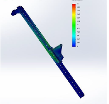
During the initial design phase of the EML product line it was thought that it may be possible to reutilize existing Berminghammer crane mounted lead section designs as the basis for the lead column. However, it became clear that the existing crane lead columns were not going to work on the EML systems because they were much too robust and prohibitively heavy for the EML. The weight of these components would overload the excavator and we would not be able to meet the desired functional specifications that the sales group had developed. Preliminary weight estimates were defined for each component which without pile, hammer and anvil, came out to 10,800 lb for the EML30. This would require almost all components to be a new design, re-thinking each component and ensuring it was well optimized for the expected loads but lighter han their higher load counterparts. In the end, the final weight of the EML30 came out to 8,700 lbs. Using Soildworks® 3D design software, several iterations of lead design were analyzed using finite element analysis (FEA) to ensure acceptable levels of stress were not exceeded. Screenshots from the software can be seen in figure 2.
Hammer Drop Design
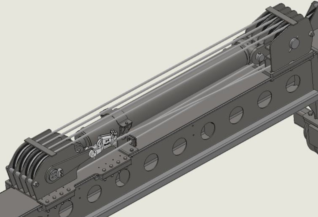
In addition to designing the structure that supports the drop hammer, performance of the drop hammer was a key requirement. The hoisting system that lifts and drops the hammer had to be quick and introduce very little losses in acceleration when compared to a free fall drop hammer. The optimal solution was to utilize a hydraulic cylinder with a multi-part sheave block on a slide, this can be seen in figure 4. The benefits of multi- parting the hoist line was a decrease in the required length of the hydraulic cylinder for full travel of the hammer down the length of the lead. It also allowed the cylinder to operate at a slower speed than the hammer Figure 4: Drop Hammer Cylinder Between two Shave Blocks falls. An experiment was conducted to assess several different methods to decrease the losses caused by hydraulic oil racing back to the excavator tank during the quick drop mode. In the end, the result was a system with drop speeds comparable to that of a free fall setting on a winch but also avoiding the spooling issues.
Excavator Integration
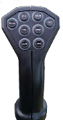
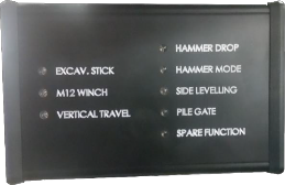
We visited the client to take measurements of the excavator, update capacity calculations and confirm range of motion of the system. Berminghammer also developed a control system that includes a joystick that mounts to the excavator’s existing bucket/boom joystick (figure 5), an active function indicator panel and electrically operated hydraulic diverter valves. Our EML systems utilize the existing bucket and stick circuits of the excavator for hydraulic flow to the EML. Functions include the stick function to control lead angle fore and aft, side-to-side tilt to allow for unlevel ground, vertical travel of the lead (EML45 and up), pile line winch & drop hammer lifting cylinder (both positioning and drop mode).
PDA Testing
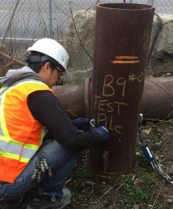
One of the required design criteria was to determine the load the EML30 could prove while driving a pile. The preliminary design suggested the drop hammer was to have a mass of 3,650kg and our stroke was suggested to start at 1.2m to give a potential energy of 43,000 Joules. The speed at impact would theoretically be 4.87m/s but our verified yard testing showed an actual 3.83m/s. From our testing data, we determined that the deceleration takes place over 4.2 milliseconds (or one frame at 240 frames / second). This yielded a deceleration of 890m/s2. Losses due to a pile anvil further decreased the force by a factor of 0.3 to yield approximately 1,000kN. It became apparent through analysis of MTO projects that many of the shoring and bridge abutment piles the EML30 would need to drive would require, at minimum, a ULS of 1,600 kN. We were 600 kN short. The designed drop was increased to approximately 2.2m to accommodate this requirement and Berminghammer enlisted EXP Services to conduct a PDA (dynamic test) see figure 6. The test resulted in confirmation that the EML30 drop anvil could prove the required ULS of 1,600 kN based on a drop height of 2.2m
EML30 – First Major Construction Project
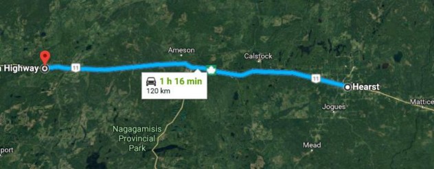
The EML30’s first project was MTO 2017-5128. It is approximately 120 km West of Hearst – see figure 7. There were three major culvert replacement sites: Site 39W-117/C Site 39W-118/C Site 39W-119/C.
Geographic Location
Hearst, Ontario is approximately 1,000km away from Berminghammer’s plant in Hamilton, Ontario.
Scope
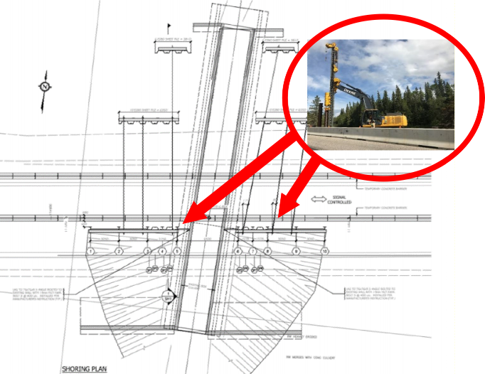
The project featured three culvert replacements on HWY 11 TransCanada (primarily a two-lane highway). This section of highway 11 is particularly remote, cellular service does not reach the site, about and hour and a half west of Hearst, Ontario - See Figure 7. As it is the only highway in the region connection East to West Canada, it could not be closed but could be reduced to one lane. The active lane of traffic needed to be supported by a shoring system. Of the three culvert replacement sites 39W-119 was the most challenging. The cut required to gain access to remove the old culvert was approximately 35 feet below road elevation. The combi wall shoring system consisted of 12x74 H-Piles and EZ-80 sheets as a well as traditional hardwood lagging. Berminghammer engaged a geo-structural firm to design a shoring system to pair with the features of the EML30. The design resulted in a combi wall system involving H-Piles to be driven first followed by sheet piles between them. This design would divert water around the excavation allowing the culvert replacement to take place in a drier environment. The outer sides of the shoring system were done by traditional H-pile (installed by the EML30) and timber lagging. Additionally, two layers of tie rods were required, anchored to four different deadman (sheet pile) walls on the other side of the roadway. Figures 8 and 9 show the design.
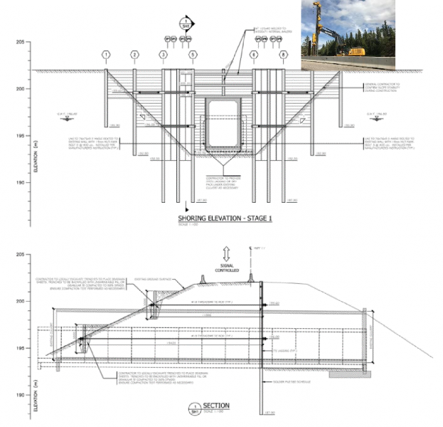
One can observe the HWY 11 Culvert 119 shoring system design in figure 9. The main shoring wall for the cut was to be installed on site using the EML30 to drive the H-Piles and sheets. The H-Piles with interlock already attached were installed first. This was to allow for the sheet piles to be threaded in and supported vertically between them. This eliminated the need for a template and increased the speed of installation.
The 4 deadman walls were pre-laced and tied together at Berminghammer’s shop in Hamilton so that they could be dropped into an open cut provided by the excavator. The two levels of tie bars were installed in stages by a local horizontal drilling contractor when the excavation had been completed to the required depth. Figure 12 shows the excavation at approximately 12 feet, immediately prior to drilling the anchors. The second and third culverts on this project, C118 and C117 respectively, had similar design with respect to the shoring wall however were not as deep a cut as to require the deadman walls and tie bars. All three roadway protection systems were installed in 5 weeks. Figures 10 and 11 show the exposed shoring wall of the shoring system for Culvert 119. Figure 10 was taken at an approximate excavation depth of 12 feet and Figure 11 was taken upon the installation of the new culvert section. In figure 11 the line of tie anchors is evident on the walers spanning the driven piles
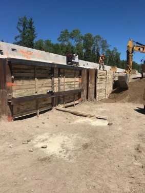
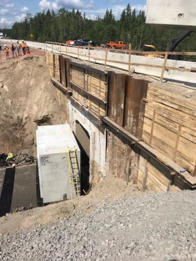
Figure 11: Completed Shoring Wall at HWY 11 Culvert 119
Advantages & Cost Savings - $68,300 (5-week case study project)
To examine the financial savings of the EML30, one can look to 3 different areas. For our case study, we will examine a 5-week piling project.
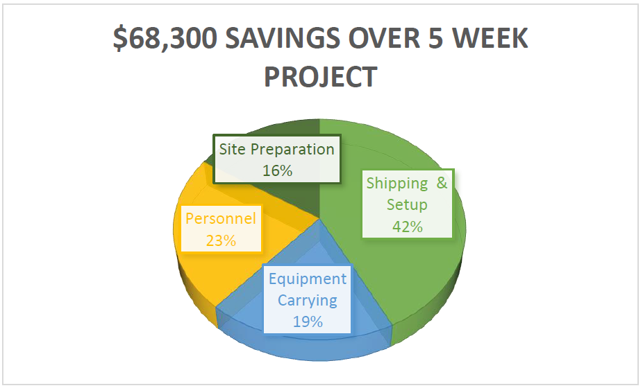
Shipping & Setup - $29,000 Saved over a 5-week Project
To understand the shipping savings component of the EML30 one must understand how this type of foundation work is typically done. Most often, crane mounted lead systems with pile driving hammers are utilized. An example is shown in Figure 12. While they are efficient in terms of installing the piles without splices they can be expensive to mobilize. They are very advantageous when there are a high number of long piles on a project because they reduce the amount of onsite welding and waiting for the crane that is holding up an additional section of pile while the welder is splicing it vertically in the air. However, to mobilize a crane mounted lead approximately 3 truckloads are required. A float for the crane carbody, a truck for boom sections and to a truck for a traditional lead system and diesel pile driving hammer. The crane mounted lead system is shown on the left in figure 12 and the EML is shown on the next page.
In the instance of mobilizing to Hearst Ontario from Hamilton, the total of the mobilization would be approximately $12,450 for a crane and lead system. The return load would be approximately the same amount yielding $24,900 in straight mobilization costs. Add the cost of the crew at $4,000 per day and include four days (site rig-up and rig-down) the total cost of mobilization increases to $40,900.
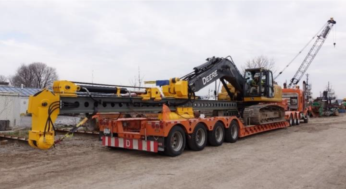
The mobilization of the EML30 is just one float. This was a key design feature planned for the EML30. The combined weight of the entire system needed to stay under 65,000 lbs to be shipped on one float. You can see the resulting shipping arrangement in Figure 15.
Because the shipping configuration could be reduced to the one float, a trip from Hamilton to Hearst Ontario could be accomplished by spending only $5,950 one way or $11,900 return. There is also no requirement for onsite assembly when the EML30 is shipped assembled.
In conclusion, when comparing the Lead mounted system and EML30 a savings of $29,000 was recognized. The freights quoted can to Berminghammer can be seen in figure 14.
Equipment Carrying Costs - $13,000 Saved over a 5-week Project
In terms of equipment, a crane and crane mounted lead system as shown above would cost approximately $2,000,000 new from the factory. An EML system complete with excavator would cost approximately $650,000.
This would translate to $3,850 per week for the crane mounted system and $1,250 per week for the EML system. For our case study, we consider a 5-week job. This translates to $13,000 of savings over the 5-weeks in equipment costs.
Personnel - $15,500 Saved over 5-week project
When a foundation contractor is retained to complete a project a crew of two people typically operate a crane mounted lead system, the crew is typically comprised at a minimum of one crane operator and a front-end man. This crew would be overseen by a project manager.
In the case of the EML30 excavator mounted piling rig, the crew is again comprised of two individuals, a front-end man but instead of a crane operator, the EML30 is run by the excavator operator. Unionized crane operators typically demand $65+ per hour, whereas excavator operators yield $35 per. The $30 per hour difference can translate to $6,000 of labour savings over the course of a 5-week project.
As the crew is comprised of members of a general contractor’s team already, there is no need to assign an additional project manager. Thus, the savings pertaining to the reduction in personnel amounts to approximately $9,500 over the course of 5 weeks in overhead.
Site Preparation - $10,800 Saved over 5-week project
The requirements for site preparation for a crane mounted lead system are substantial mostly due to the size of pads required for cranes. One must have a stable working platform and enough space to boom the crane and lead combination up and down.
In the case of the HWY 11 project, should the roadway protection have been installed by a traditional crane mounted lead system there would have needed to have been an additional $10,800 worth of gravel supplied to the site; $3,600 per truck. This additional material is not required with the EML system as it takes a much smaller footprint.
It is worth mentioning that for this project it may have been impossible or highly cost prohibitive to complete the shoring system utilizing a crane because of the proximity to the water on the southern side of the road. There was a mere 19 feet of space to utilize to drive piles before the aggressive slope towards the river began.
Continued Uses Since the First Project
Since the first utilization of the EML30 in Hearst, Ontario, BOT next utilized the EML30 to install a similar shoring system in Southern Ontario at the QEW/403 junction, see figure 17. After that Powell Foundations rented the EML30 from BOT for a shoring system for a bridge replacement on HWY 401 at Brock Road. Stephen Foster of Powell, in response to the below photo from figure 15, stated “Thanks Dave, the Powell Foundations Inc. crew really enjoyed trying out this rig to complete this tight access project. Thanks also go out to BOT Construction for letting us rent their rig for this project.”
Copyright (c) Berminghammer Foundation Equipment, 2019.
Berminghammer is a wholly-owned subsidiary of 

